Epson 4900

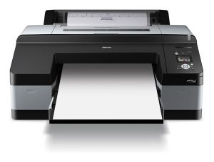
Within the photography studio we now have an Epson 4900 for you to use. This wonderful machine sadly led a sheltered life for a while, but with a little tlc she’s back in business and ready to print*

ES_Pro_4900_Front_w.paper_

Features:

  • Sheet based media from A4 up to A2+
  • Paper thickness’ from 0.08 mm – 1.5 mm
  • 12 inks that can reproduce 98% on the Pantone colour range
  • Very good registration for double sided printing

The machine is hooked up to an iMac that has Adobe CC installed and has a colour calibrated screen to help you reproduce your artwork more accurately. To book time on the printer, simply email Robbie on mr22@gre.ac.uk

There will eventually be a small fee to cover the cost of the inks, although this is not in effect at this time.

Top tips!

Whilst the printer will print on any paper type, ink will tend to bleed on non treated paper. Please make sure your paper is inkjet compatible for the best results.

If you which to print double sided and without ink bleed, please ensure your paper is treated on both sides, as 90% of inkjet paper is only treated on one side.

Borderless printing is only achievable on A4 & A3 paper sizes and quality is not guaranteed 3mm from the edge

It is best to use paper larger than you need for double sided printing so that you can print crop/trim marks

Double sided printing is not possible direct from inDesign, it is best to print from a PDF or a Jpeg/PSD file


*As mentioned above, a bit a work has has gone into bringing this machine back to life. She is still not printing perfectly with some images having faint lines running through them due to the Light Grey printhead not yet printing up to spec. This will dissipate with use however as these types of machines need to be used regularly to keep in tip top shape. Due to this, we will not be charging for the printers use until this minor fault has corrected itself, all we ask is that you supply your own paper.

Dragonframe – Basic setup

00 LogoA brief introduction to running Dragonframe (3.6.5) stop motion capture software within one of our four animation suites.

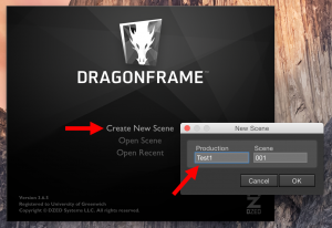
Step 1. Open up the Dragonframe software and select ‘Create New Scene’

01 getting started

From here you will then need to give your project an abbreviated title. Scenes will start at 001, allowing you to create many scenes that all have the same title. For ease of navigation, it makes sense to create your file on the desktop when prompted where to save your work. All of your individual captures will be stored within this folder as you make progress, as well as any test shots.


Step 2. Camera setup. Check that the camera is connected to the computer via it’s USB lead and turn it on. Ensure that the camera is set to MANUAL mode and that Auto Focus* is turned off.

*located on the lens

02 Camera setup
03 camera setup
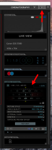
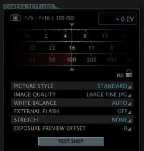
Dragonframe has two main view modes. Camera Setup, and Shoot mode. Click on the Camera icon, located top right of the application, to access the Camera Setup view. From here you have complete control over your camera settings. The settings within the image on the right are a good starting place, yet feel free to have a play get a the feel for how they affect the image.

Saying that, some settings should avoid being changed. These are:

ISO which you should keep at 100 to minimise grain and IMAGE QUALITY should be left at LARGE FINE JPG. Ideally WHITE BALANCE should be adjusted to your lighting type, AUTO should only be used as a last result if the other presets are giving you an unwelcome colour cast.


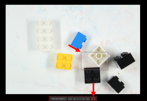
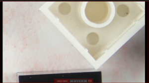
Step 3. Check your focus. If not already visible within the live view screen, click the window icon highlighted below. Once checked, a window will appear within the live view area they you can move to a location of your choice. Once an area is highlighted, click within the window for a zoomed in view of your selection. You can now use the focus ring on the front of the camera lens to focus your image with confidence.

04 Focus assist 05 focus assist 


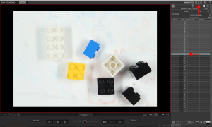
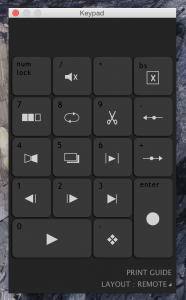
06 Shoot mode Step 4. Shoot mode. To enter shoot mode click on the Screen icon next to the Camera 11 screen keyboard controlsicon located top right of the application. By using either the on screen keypad (on the right) or the keypad located on your keyboard, you’ll be able to Shoot, Play, Cut, Delete, Loop and more. As you shoot, your captures will appear within the table on the right. X represents a capture C represents the current image shown on screen via live view.

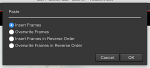
To delete a capture, simply click on the appropriate frame within the table and hit BackSpace on either keyboard. It is also 08 copy paste framespossible to copy and paste frames to save time when making repetitious scenes.  Just click and drag over the frames you wish to copy within the table and either use the tool bar to navigate from EDIT down to COPY, or hit cmd+C to copy the pictures. Now click within the table where you would like the frames to go and either navigate from EDIT down to PASTE or hit cmd+V, you’ll be presented with a window displaying four Paste options.


10 onion skin

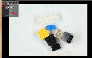
Step 5. Onion Skin. A most useful feature within Dragonframe. To turn Onion Skin on, navigate to the tool box located at the top left of the application. This tool box become invisible after a few seconds of inactivity, just move the mouse over that area to make is visible again. The Onion Skin tool is the third icon from the left. Once active, you can use the slider to make either the previous frame appear as a transparent image that overlays the live view. This allows you to more accurately adjust your movements between frames, equally it is a useful tool that can be used to reset your subject matter if they are moved accidentally or are continuing at a later date.


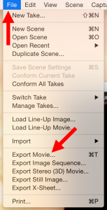
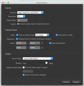
12 export  Step 6. Saving your work as a movie.13 export By navigating from FILE down to EXPORT MOVIE you will be presented with an export menu. The setup within the example screenshot would be a good guide for those starting out. Depending on your desired output though, there are a few options that can be controlled via this screen, some of the most important being Frame Rate, Scale and Media Type. Your Frame Rate dictates how many frames will be displayed per second. The higher the number the smoother the animation, yet the many more frames you’ll need to shoot to pull this off. Scale is used to dictate the size of your movie on screen. Bare in mind that full frame images from the camera are not the same proportion as standard wide screen, although a tick box will allow you to override the proportions if you so wish.


Machine Restrictions on Design Studio Machines

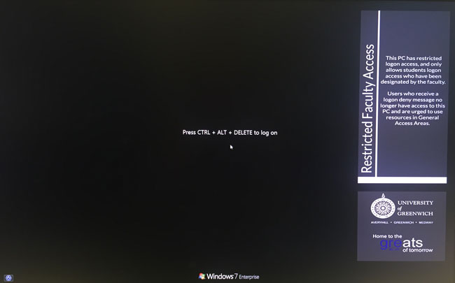
Machines in the first floor design studios are now login restricted just to staff and students of the two departments of CPDA and Architecture & Landscape.  If you are a student or staff member of another Department or Faculty then you will not be able to login.  We would ask that non department users visit the library open computing spaces, or those in King William, Queen Anne, Queen Mary, etc.  The University of Greenwich mobile app can show where there are free machines for use elsewhere on the campus

restricted


We have brought in this restriction so that department students can access specialised software and equipment that is unavailable elsewhere in the University.  There are two large format plotters in the library plus A1 scanner.


New workshop Equipment: T65 Sliding-Table Saw

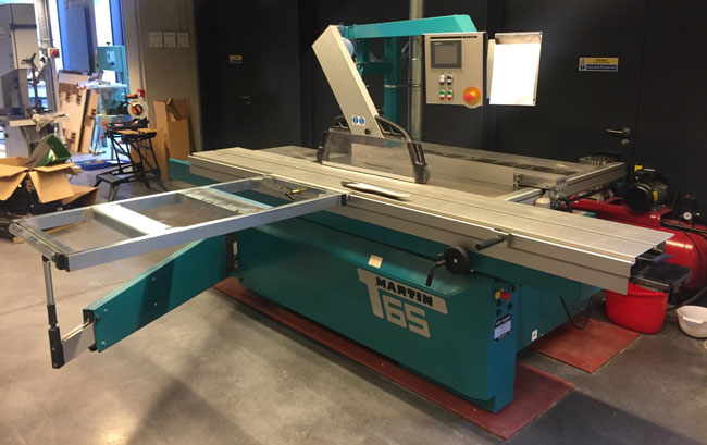
We have a new sliding table saw, or panel saw in the workshop – a Martin T65 Sliding-Table Saw

panel-saw

This is a sawing machine with a sliding table that can cut large sheets of wood, perspex, laminates, plastics etc cleanly and with very high accuracy.   The movement of the blade height and angle are electronically controlled and the machine always knows the saw blade width and diameter.  It has a large cutting height of 204 mm and a tilting angle of 0 to 46° to provides greater flexibility for complex tasks.

This machine is operated only by qualified technical personnel. Please contact the Stockwell Street workshop for further information


Christmas Break Opening Times

The opening times over the Christmas break are as follows

Design Studios

  • Closes:  Thursday 24th December 2015; Midday
  • Reopens:  Monday 4th January 2016; 8.00 AM

Workshop

  • Closes: Friday 18th December 2015; 4.30PM
  • Reopens: Monday 4th January 2016; 10.00 AM

Photographic Studio

  • Closes: Friday 18th December 2015; 4.30PM
  • Reopens: Monday 4th January 2016; 10.00 AM


TV Studios / Editing Suites 

  • Closes: Thursday 24th December 2015; Midday
  • Reopens: Monday 4th January 2016; 10.00 AM


Note: the Library building will be re-opening on Saturday 2nd January – they have two plotters there.

Have a good break!


Wireless Printing from MAC / PC Laptop to MFD Printer

You can print to the MFD printers found in the print area (and in the library) from your own laptop (Mac or PC) as long as you are on the University GreenNET or Eduroam wifi network

This machine prints A3 / A4 mono or colour.

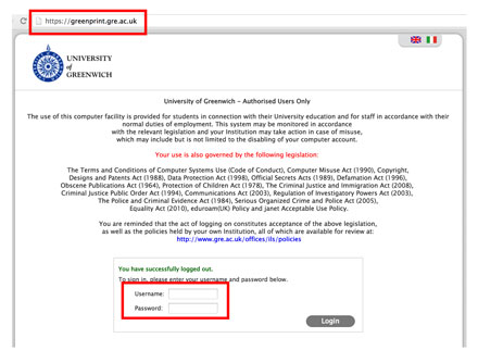
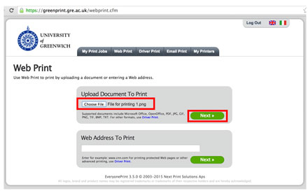
1. To print wirelessly you need to access the GreenPrint page at https://webprint.gre.ac.uk

2. Log in with normal username and password

greenprint-1

3. Upload the document that you want to print by clicking the ‘Choose File’ button and navigating to it, then click ‘Next’ – files accepted are:

  • PDF
  • MS Office (Word / Excel / Powerpoint)
  • Image files in the following format – JPG / GIF / PNG / TIF / BMP

greenprint-2

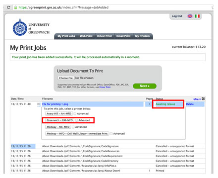
4. The document will process for a few seconds and then show its status as ‘Awaiting release’

greenprint-3

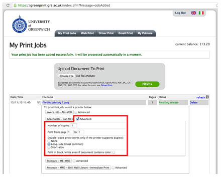
5. Select the printer for use. Here, it will be Greenwich – GM-MFD

greenprint-4

6. To pick up the print you need to swipe your card on one of the printers just like you would for a regular print

Waypoints: OBJ to VR Headset Translator

“Waypoints” is our Virtual Reality (VR) conversion tool to enable users to view their 3d models in real time with a VR headset.

The software will translate files from standard 3D packages such as 3D studio, Blender, Rhino etc into a format that can be viewed on a VR Headset – or rather a mobile phone in a suitable headset holder like Google Cardboard.  The converted file is loaded into the browser window of a mobile phone and fitted inside the headset where it will respond to head movement to allow the user to look around their design.  Additionally “waypoints” are generated around the model to let users navigate around the VR space;  simply “stare” at one of these points to select it, then that point is moved towards.

‘Waypoints has been developed for the department by Joe Green, using three.js and NW.js.’
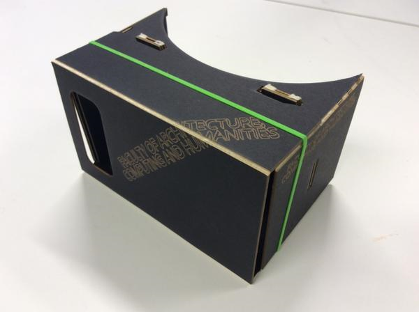
vr-headset

Instructions

Waypoints Beta r1 Documentation

This is beta software and may contain bugs.

You will need:

  • A copy of Waypoints.
  • A Windows PC and a mobile device connected to the same wifi network.
  • A mobile browser with WebGL support (most modern smartphones and tablets will have this)
  • A VR viewer for your mobile device, such as Google Cardboard.
  • Mongoose Binary Free Edition (‘the easiest to use web server on the planet’). Download it from https://www.cesanta.com/mongoose.

Getting Started (Windows 7)

Copy the Mongoose Free executable file to a newly created folder in an accessible location such as the Desktop.

Open Waypoints. It will start up with a basic demo scene already loaded. Click ‘Export HTML’ (at the bottom of the panel on the right). Save the file in your Mongoose folder.

Minimise Waypoints for the moment and browse to your Mongoose folder (it should now contain a copy of Mongoose Free and a file called index.html). Double click the Mongoose icon and index.html will open on your computer. Ignore that, and check the system tray for a yellow Mongoose icon. Click the icon, and look for a menu entry that begins ‘Go to my address:’. Carefully type the given address into the browser ON YOUR MOBILE DEVICE and the demo VR scene should load. Attach your VR viewer to your device and you should be good to go (you may need to turn around to find the scene). Keep the floating crosshair aligned with one of the cyan spheres for one second (until it fades out) and your virtual viewpoint should animate to that location.

So long as Mongoose is running, all you need to do to update the scene on your device is make changes in Waypoints, overwrite index.html, then refresh the browser on your device. Once set up, it should be quick and easy to experiment using this method. To stop Mongoose, just click its icon in the system tray and choose ‘Exit’.

Note: University machines will require administrator permission to run Mongoose properly as it requires firewall changes; you will need to get one of the technical staff to open a port for you.  Alternatively use your own laptop which you will (presumably) have administrator access to.


Importing Models and Textures

Drag and drop a 3D model (.obj format) or a texture (.jpg or .png) onto the window to replace the currently loaded model or texture. To import multiple objects, you will need to export them from your 3D modelling software as a single .obj file. Waypoints does not currently import normals or provide realtime lighting, so your model must be UV unwrapped and textured. Lighting and materials can be ‘baked’ into a single texture as per the demo scene. The pixel dimensions of your texture should ideally be powers of two (256, 512, 1024 etc) and your texture should not exceed 2048 x 2048 pixels in size. 1024 x 1024 is the recommended maximum, and should allow for a reasonable amount of detail.

Instructions on how to generate UV mapped textures varies between 3D applications; see this link for instructions on Baking Materials in with Blender


Top Viewport

The top viewport gives an overview of your scene.

  • Left mouse button – rotate view
  • Middle mouse button (or mouse wheel) – dolly in/out
  • Right mouse button – track left/right, pedestal up/down


Left click a waypoint to select it, and drag the transform gizmo to move it around.

  • Red arrow – x adjustment
  • Green arrow – y adjustment
  • Blue arrow – z adjustment


  • Yellow plane – xy adjustment
  • Cyan plane – yz adjustment
  • Magenta plane – xz adjustment


Note that the coordinate system used (which is dictated by WebGL) may differ from your 3D modelling software.

The amber coloured pyramid extending from the currently selected waypoint represents the extents of the view from that location. This view is always displayed in the bottom viewport.


Bottom Viewport

The bottom viewport shows the view from the selected waypoint. Drag the view to look around and find out what will be ultimately be visible by turning your head in the exported VR scene.


Panel on Right


Drag values up or down to modify them, or click to select then edit using the keyboard.


  • World > Hue / Saturation / Brightness – Set the background colour of the scene.
  • Waypoints > Hue / Saturation / Brightness – Set the colour of the spherical markers
  • Waypoints > Sphere Diameter – Set the diameter of the spherical markers. If your waypoints are spaced a long way apart, or you have chosen a wide angle focal length setting, you may need to increase this to enable the viewer to easily get a ‘lock’ on distant waypoints using the floating crosshair.


Selected Waypoint > X / Y / Z – Another way of positioning the selected waypoint.


Camera > Pan / Tilt – Rotate the camera. These settings will have no effect on the exported scene, as the camera orientation will be controlled by device orientation.


Camera > Focal Length – The focal length of the camera – in other words, ‘zoom’. Lower values = wide angle lens / wide field of view / exaggerated perspective. Higher values = telephoto lens / narrow field of view / flattened perspective.


Stereo > Separation – The distance between the two virtual cameras used to create the stereoscopic effect. Increasing this will increase the impression of depth in the exported scene, but at some point it will become difficult or impossible for your brain to fuse the left / right images.


Stereo > Projection Plane Distance – Objects closer than this will appear to pop out of the screen toward you, while objects further away will appear to be ‘behind’ the screen.


Not all combinations of Focal Length, Camera Separation, and Projection Plane Distance will work, and small changes can quickly destroy the 3D effect or make for an unpleasant viewing experience. Aim for viewing comfort rather than ‘extreme 3D’. Further technical info on these parameters can be found here:

http://paulbourke.net/stereographics/stereorender/


Export > Export HTML – Export your edited scene for viewing using Google Cardboard or similar (see ‘Getting Started’ above).


ArcGIS – Software for Students

ArcGIS 10.3.1 for Desktop is now available to students.  Full hardware / software requirements are here but broadly you need a PC running 64 bit Windows 7, 8 or 10.  Apple OSX is not natively supported though virtualised and BootCamp versions of Windows have been seen to work.

There is a form that must be filled in before you can have access to the ArcGIS install DVD.  Once you have filled in this form then it should be given to your ArcGIS tutor

ArcGIS Student Copy Application Form

The software can then be obtained in the form of an ISO file which you must burn to DVD or install via a virtual CD drive (advanced)

How to burn an ISO from Windows 7

Advanced users may want to install without burning a DVD by utilising “virtual drive” with Magic Iso

Once you have your DVD (or virtual DVD) you can use this PDF file to carry out the installation.  Note: The procedure here is written for ArcGIS 10.1 – it may differ from 10.3 cosmetically but the procedure is the same.

ArcGIS-Desktop-10-Installation-2013-2014


Top Ten Printing / Plotting Issues

Here are some common issues and solutions that can occur in the computing areas:

Issue: Print is sent but but the PCounter Popup window telling you the print cost *DOES NOT* appear

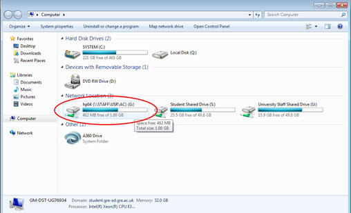
Solution: Check your G Drive – if there is no space free there then delete some files (click start – my computer – look at “G” drive).  Look in your documents folder, desktop etc. Delete or move files so that G drive does not show red.

g-drive

Start – Computer
If your G Drive shows up in red then you are too low on space

[divider] 

Issue: Nothing is printing, but the PCounter Popup window telling you the print cost *DOES* appear
Solution: CHECK BALANCE has credit (you can check by trying to print an a4 and watch what the popup says; then cancel the print).

Note: if your print is going to cost more than what is in your account then it will NOT print your file.  If you then top up your account you will have to send it again.

[divider]

Issue: The correct printer / plotter does not appear in the drop down list:

Solution: Printers are meant to be setup on login; if this doesn’t happen you can force them in using this method:
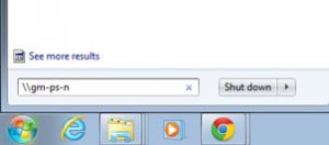
– Press the Windows Start button
– In the search programs and files text area type \\GM-PS-N

gm-ps-n

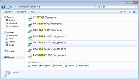
– This brings up a window with a list of lots of print queues – in the top right hand search windows type DST
– This shows only the printers in the print area; double click the one you want to print to

printer-list
– The printer queue is installed and will now be available from the print choose drop down menu
– NOTE: to add the A3/A4 colour / mono MFD printer type in MFD into the printer search windows instead of DST and choose the printer GM-MFD-STU-COLOUR

[divider]


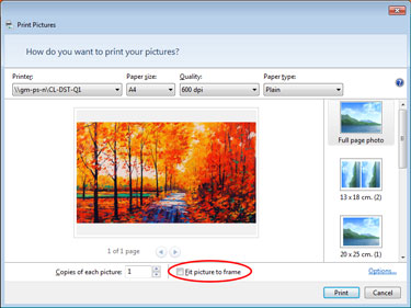
Issue: Printing files from Windows Photo Viewer but image prints out small in the corner
Solution: always untick the Fit Picture to Frame click box

dont-fit

[divider]

Issue: PDF not plotting at all / plotting with chunks of graphics missing but taking money
Solution: Complex or large PDF files can be cause problems for printing; e.g. if they have many layers in them.  Tricks to get around problem PDFs include:

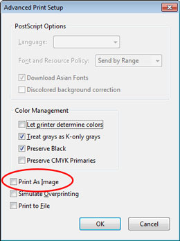
– In Adobe Acrobat from the print dialogue select Advanced then Print as Image

print-as-image

– In extreme cases you can drag the PDF file into Photoshop.  This will rasterise it to make it a flat image (if you keep the resolution at 300dpi there will be no loss of quality or sharpness).

[divider]

Issue: Sheet feed plotter – someone’s file is ready to print but they are not there to print it and someone else is waiting.

Solution: if someone has a job ready to go but they have not come to feed the paper then please wait at least 10 minutes for them to come back. Then either:

a) Be kind and feed a sheet of paper for them

b) Be unkind and ask one of the support staff to cancel that job


Baking in Lighting and Materials for use with VR Headset

For 3d models to retain their texture mapping and lighting when translating into VR compatible files you need to “bake” these textures into your model first.  Otherwise the model will just show as a flat solid white colour.

The process for this varies according to the 3d software –

 This is the process for Blender (tested in version 2.76)

blender

Create your model, add materials and set up lighting as required.

– Note: Stick to ‘Diffuse BSDF’ and ‘Emission’ surface types when creating materials.

Combine multiple meshes by selecting them and pressing Ctrl + J (not crucial but seems to simplify things). Then:

  1. Unwrap the mesh (3D View)
    Select the mesh, press space, start typing ‘Smart UV Project’. Choose it from the list when it appears and click OK
  2. Create an image to bake to (UV/Image Editor window)
    Click the ‘New’ button to create an image. Name the image (eg ‘baked’), leave the width and height at 1024 px, uncheck ‘Alpha’ and click OK.
  3. Select a material (Properties window > Material settings)
    Select a material from the list at the top.
  4. Set image to bake to (Node Editor window)
    Click Add > Texture > Image Texture then, in the orange-highlighted ‘Image Texture’ panel that appears, click the small image icon and select the image that you created in step 2 (‘baked’).
  5. Repeat steps 3 and 4 for every material used by your mesh.
  6. Bake materials and lighting (Properties window > Render settings)
    Scroll down to the ‘Bake’ settings, uncheck ‘Clear’ and click the ‘Bake’ button. Noise can be reduced by increasing the number of render samples under ‘Sampling’ in the render settings.
  7. Save the baked image (UV/Image Editor window)
    Click Image > Save As Image.