Centro Cultural CEINA, Santiago — May/June 2026
The Exhibition
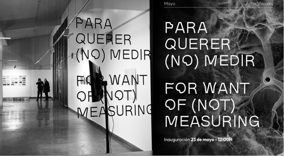
Para Querer (No) Medir / For Want of (Not) Measuring is a collective exhibition that has been travelling internationally, initiated by artists Jim Hobbs and Patrick Adam Jones as an ongoing series, each iteration landing in a different city with different curators and invited collaborators. The Santiago edition was curated by Joselyne Contreras and Jorge Cabieses-Valdés, who brought together a group of Chilean and international artists at Sala Expo 1 of Centro Cultural CEINA – a cultural centre housed inside the historic Instituto Nacional building in the heart of the city.
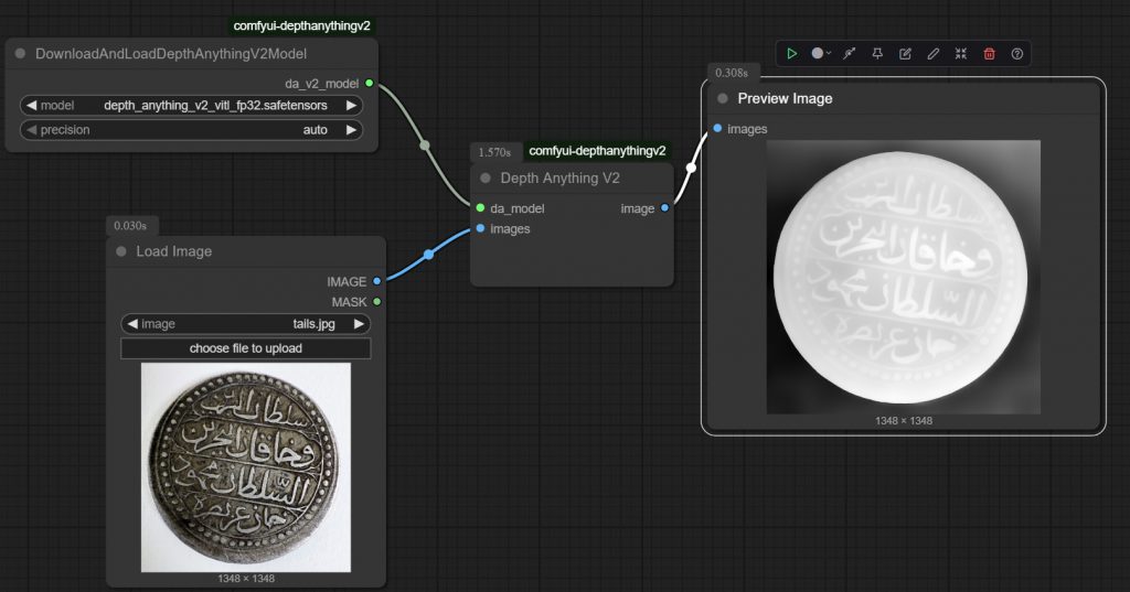
The title frames the central question that runs through the work: what is it we actually do when we measure? And what do we choose not to measure – or choose not to let measuring dominate? For me, working with LiDAR, photogrammetry, Gaussian splatting, depth maps – as an expressive medium, these are significant questions. Precision instruments producing aesthetic rather than technical ends. Data becomes an image. Measurement becomes an interpretation.
I was exhibiting alongside Simon Withers, fellow member of Captivate Heritage Laboratory, along with Jim Hobbs (@jimhobbsart), Patrick Adam Jones (@patrickadam_jones), Andrés Durán (@andres_duran_d), Camila Lobos (@camilalobosd), Maria Brigita (@mariabrigita), Francisca Montes (@franciscamontes), Natalia Herrera (@nat.ssh), Jaime San Martín (@jaimesanmartina), and Jorge Cabieses-Valdés (@cabiesesvaldes). A genuinely collaborative, warm and supportive group – something that made the whole experience feel less like mounting a show and more like making something together.
The Work: Preparation (UK)
Element 1 : Very large laser scan render of sweet chesnut
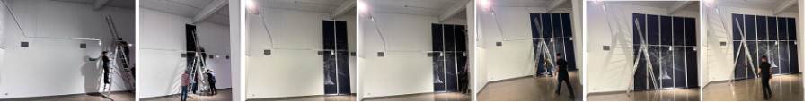
The centrepiece of what was brought to the exhibition – a laser scan render of a 365-year-old sweet chestnut tree, a single tree, captured with LiDAR, processed and rendered as a point cloud image measuring 5,400 × 5,400 mm across six banner sections. Months of work in the UK preceded a single week in Santiago.
The preparation phase was substantial; scanning the tree being the starting point. Multiple LiDAR passes registered together into a single coherent point cloud and brought into 3ds Max / V-Ray for the points to be manipulated to read correctly – adjusting density and display, and most importantly selecting a viewpoint that could carry the weight of the subject. Throughout, resolution had to stay high enough so that when the image is tiled across six strips and printed at five metres each, it remains sharp and still holds as a surface worth looking at from close range.
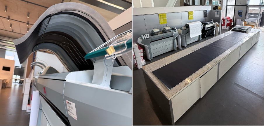
Output phase: six banner sections produced on Canon Colourwave 700s, each panel a 35-minute print run. Two copies were made – one on 120gsm coated paper, which held the deep blacks the image needs, and a backup set on 130gsm Tyvek. The Tyvek is tear-resistant, useful for something travelling in luggage to the other side of the world, but it doesn’t give the same depth – the blacks come out smoky rather than inky, which matters when the image is built from points of light against darkness.
Element 2: Small hi-res renders of tree trunks
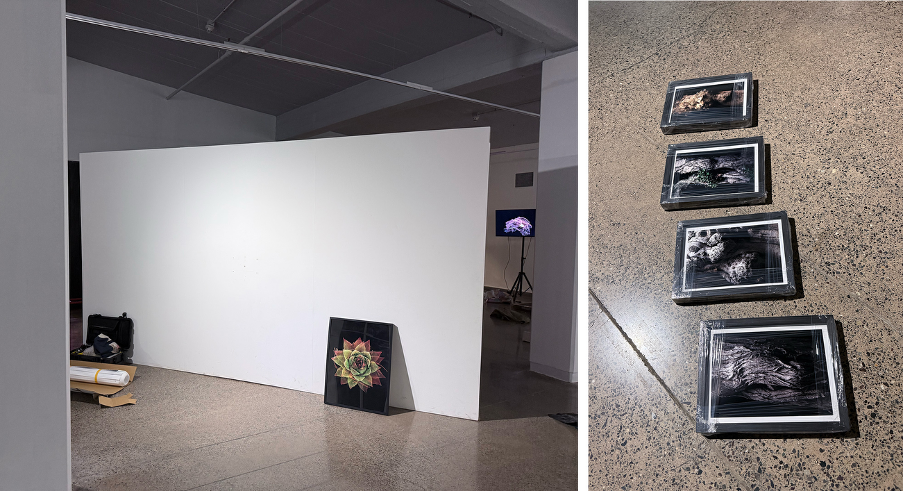
Alongside the large-format sweet chestnut banners, a set of four small, framed prints: tight, hyper-real scan renders of tree bark and trunk surfaces, printed at a scale that requires close inspection. The contrast was deliberate. A viewer would naturally walk up to the framed pieces – the detail pulling them in, the texture hyper-real at that range – then step left to find the full six-metre span of the tree demanding they step back to take it all in. The same subject, two entirely different registers of scale and body.
Element 3: (macro level) scans of seedlings / small plants.
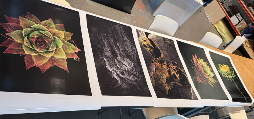
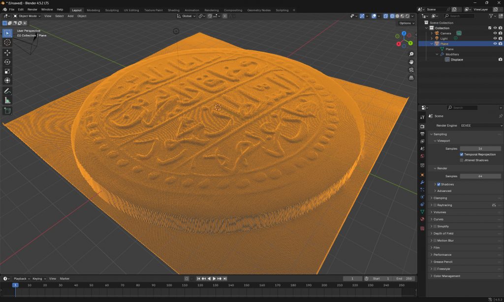
A set of ten high-resolution scan renders – the macro end of the scalar range. Each derived from 100–150 macro photographs taken in studio conditions: controlled lighting, turntable, and in some cases a rotating hanging clamp. Processed via RealityScan, CloudCompare, and Blender with V-Ray. Blender’s geometry node system treats points as geometry – unlike 3ds Max – meaning size, shape, material transparency, and lighting all become variables in composing the final render.
Element 4: animation of point clouds
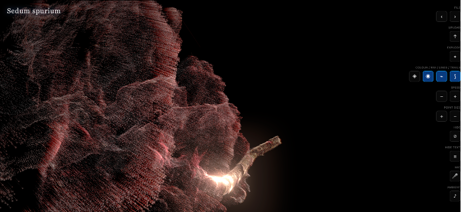
Alongside the still renders, a 30-minute looping animation of a separate set of seedling and plant scans – those that hadn’t come out well enough to present as stills. The animation is a screen recording of a semi-interactive web app in which each point cloud loads in a random orientation and applies random zooms, sweeps, and effects, with an optional sound-reactive mode. Running the live app unattended for two weeks in a gallery was too risky, so a recorded version was the practical solution – capturing the behaviour of the app without the vulnerability of leaving it live.
https://pointcloudviewer.netlify.app
Portraits in Points
This work begins with measurement – a camera tracing the surface of a living plant through hundreds of overlapping photographs, reconstructing millions of coordinates in space from light and shadow alone. Rendered through Blender’s geometry node workflow and V-Ray’s physically based shading, each point in the cloud becomes a surface, a material, a thing that catches light. The process feels less like making and more like releasing – as though these images were always latent in the data, waiting to be let out. What emerges is less a record than a portrait – the plant known not through data, but through the attempt to capture it.
The Setup (Santiago)
All of this had to travel. Two sets of six five-metre banner sections, hanging hardware, print stock, hard drives – packed into hold luggage for the 14-hour flight from London to Santiago. One becomes very aware of the fragility of physical work at that point.
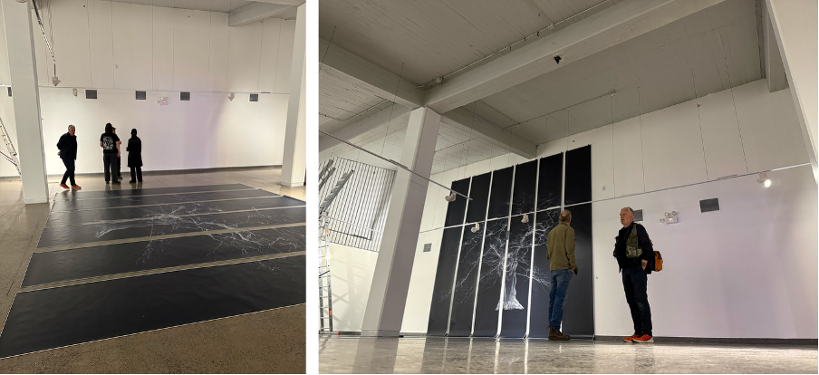
The gallery space at CEINA is a basement below a lecture hall with high walls on one side – genuinely high, which was the reason the tree banners were possible at all. Getting six-metre sections of print onto a wall without a proper rigging team requires patience, a certain amount of improvisation – and a very high ladder. The process of fixing, managing the weight and paper slip, getting the joints equal and level – it takes a day, and the work is cumulative. Fortunately, it arrived undamaged and stayed up om the wall so there was no need to swap to the reserve paper type after all.
Framing for the 10 gloss seedling prints needed to be sourced locally – some anxieties about navigating an unfamiliar city to find a frame supplier, but Santiago provided – the frames we found suited the work well and were remarkably cheap. A very ordered close 2 x 5 grid layout seemed fitting for this display wall.
The seedling animation played on a 40-inch screen on a standalone stand nearby close to the gallery entranced, a media player on a quiet loop. The animation shows each object from every angle, never settling.
Planning the layout alongside the other artists was a very rewarding part of the install. The exhibition as a whole had to function as a room – different bodies of work in conversation with each other, sight lines that made sense, space for viewers to move through. That negotiation, between artists who had never worked in the same room before, happened quickly and generously.
The opening was 12 noon on 23 May. The exhibition ran through to 25 June, open to the public Monday to Sunday, 11:00–20:00.
The Artists and the Room
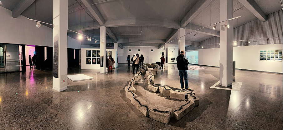
What made the Santiago edition of For Want of (Not) Measuring work as a collective show was the variety of ways each artist approached the underlying questions of scale, precision, and what gets counted. The Chilean artists brought a different set of references and preoccupations from the international contributors — and the curators’ job, which Joselyne and Jorge did so well, was finding the threads between them without forcing resolution
The group was easy to work with. There was very much a mutual interest in each other’s practices, a willingness to help during install, and a low-ego collaborative atmosphere that made the mechanics of showing feel worthwhile.
Personal Reflections
Portraits in Points
This work begins with measurement – a camera tracing the surface of a living plant through hundreds of overlapping photographs, reconstructing millions of coordinates in space from light and shadow alone. Rendered through Blender’s geometry node workflow and V-Ray’s physically based shading, each point in the cloud becomes a surface, a material, a thing that catches light. The process feels less like making and more like releasing – as though these images were always latent in the data, waiting to be let out. What emerges is less a record than a portrait – the plant known not through data, but through the attempt to capture it.
Arriving in Santiago with the work – which I would always describe as a process, or the output of a process – it was a surprise (in a useful way) to see it received as “artworks”: discussed, interpreted, and placed in relation to other exhibition pieces. This reception shifted how I thought about the work, but the fact that I don’t consider it “art” is perhaps irrelevant. Designing workflows and systems, setting parameters, then waiting to see what comes out at the other end – whether that is art depends on the viewer, but the Santiago conversations raised the idea that this question itself is the important one.
One discussion that stays with me is around whether work needs explanation, or whether it should simply be put out there for the viewer to interpret blind. My instinct – certainly for this work – is that explanation matters. Scanning / processing / rendering is not something most people would be aware of, or aware has been used to produce what they’re looking at. One can look at these images and find them interesting or pleasing without knowing anything about their origin, but it’s the technology and the process behind them that makes them genuinely interesting to me. I’m aware I may be too close to this to be objective, but I feel the visual output is almost a byproduct of the process (the most important thing). I’m still not fully convinced that an uninformed viewing / reading is necessarily the richer one.
Another reflection is that there’s a sense in which this work is just cleverer than I am. The workflow produces things I couldn’t have designed or predicted. I set the conditions, build the system, choose the parameters – and then something comes out that surprises me. The intelligence, if that’s the right word, is distributed across the process rather than concentrated in any single decision I made. In a way, it just happened. That’s a curious thought, but perhaps the most honest description of how it feels.
What Santiago made clear was that work on its own – on a workstation screen – becomes something else when placed beside unfamiliar artists in an unfamiliar space. The role of the curator is not just organisation and layout, but interpretation – that’s key. The decisions Joselyne and Jorge made changed what the work meant – not in the sense of any loss of ownership, but by no longer being mine alone, it has another life.
Exhibition details
Para Querer (No) Medir / For Want of (Not) Measuring
Centro Cultural CEINA, Arturo Prat 33, Santiago
23 May – 25 June 2026
ceina.cl