A digital model of the entire World Heritage Site above and below ground
A very large project founded on a very simple idea – to capture with spatial fidelity in one digital model everything of significance above ground, below ground and underwater between Rangers House and Island Gardens.
That is, to build a digital model of the entire World Heritage Site incorporating the whole Royal Park above ground, the 300 odd tunnels and several reservoirs and conduits below ground, Rangers House, the Observatories, Flamsteed’s Well, Our Ladye Star of the Sea, Queen’s House, the Maritime Museum, the Tilt Yard, Admiral Hardy’s mausoleum above and below ground, the ORNC, St Alfege, St Alfege graveyard, the Tudor palace underground and what little is above ground, Cutty Sark, the foreshore, the Thames bathymetry underwater, the foot tunnel and Island Gardens. A half valley section cutting right through the World Heritage Site uniting every element of the architecture and landscape above and below ground.
The first model of any kind to unite and link every element of the World Heritage Site.
To make a digital model of what Canaletto saw when he painted Greenwich from Island Gardens in 1750.
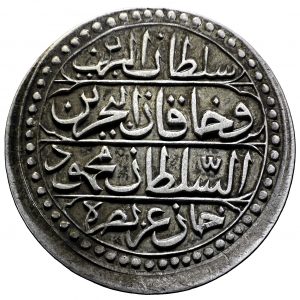
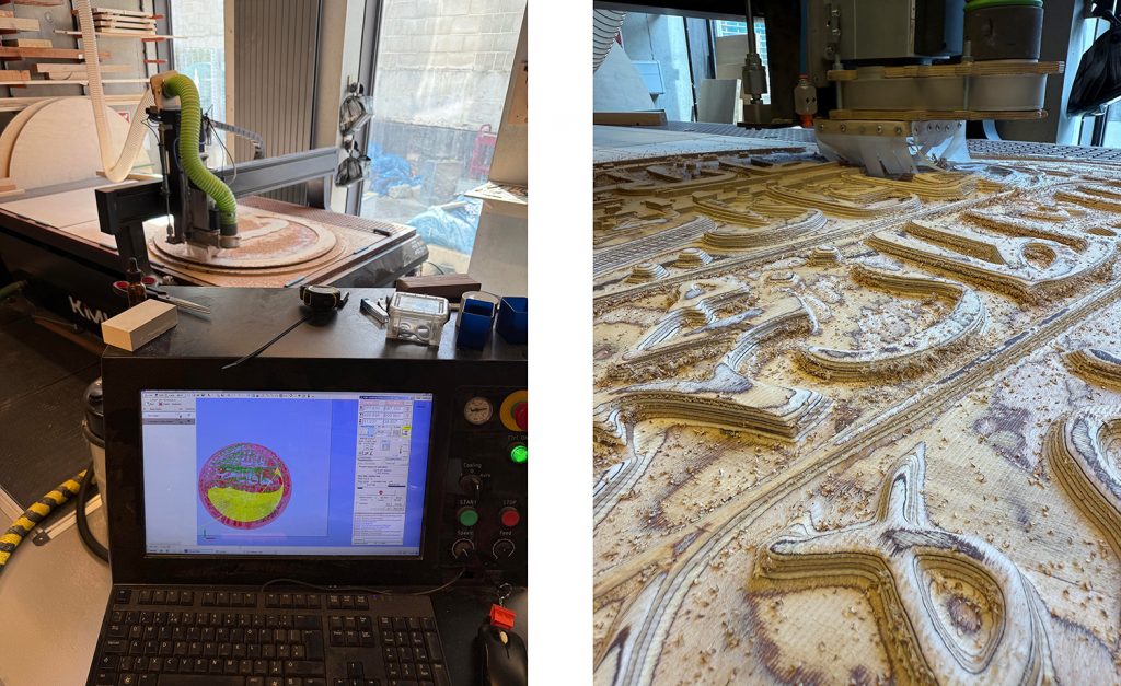
A project to capture and reproduce an 18th-century coin from the collection of Michael Talbot, Associate Professor in the History of the Ottoman Empire and Modern Middle East at the University of Greenwich.
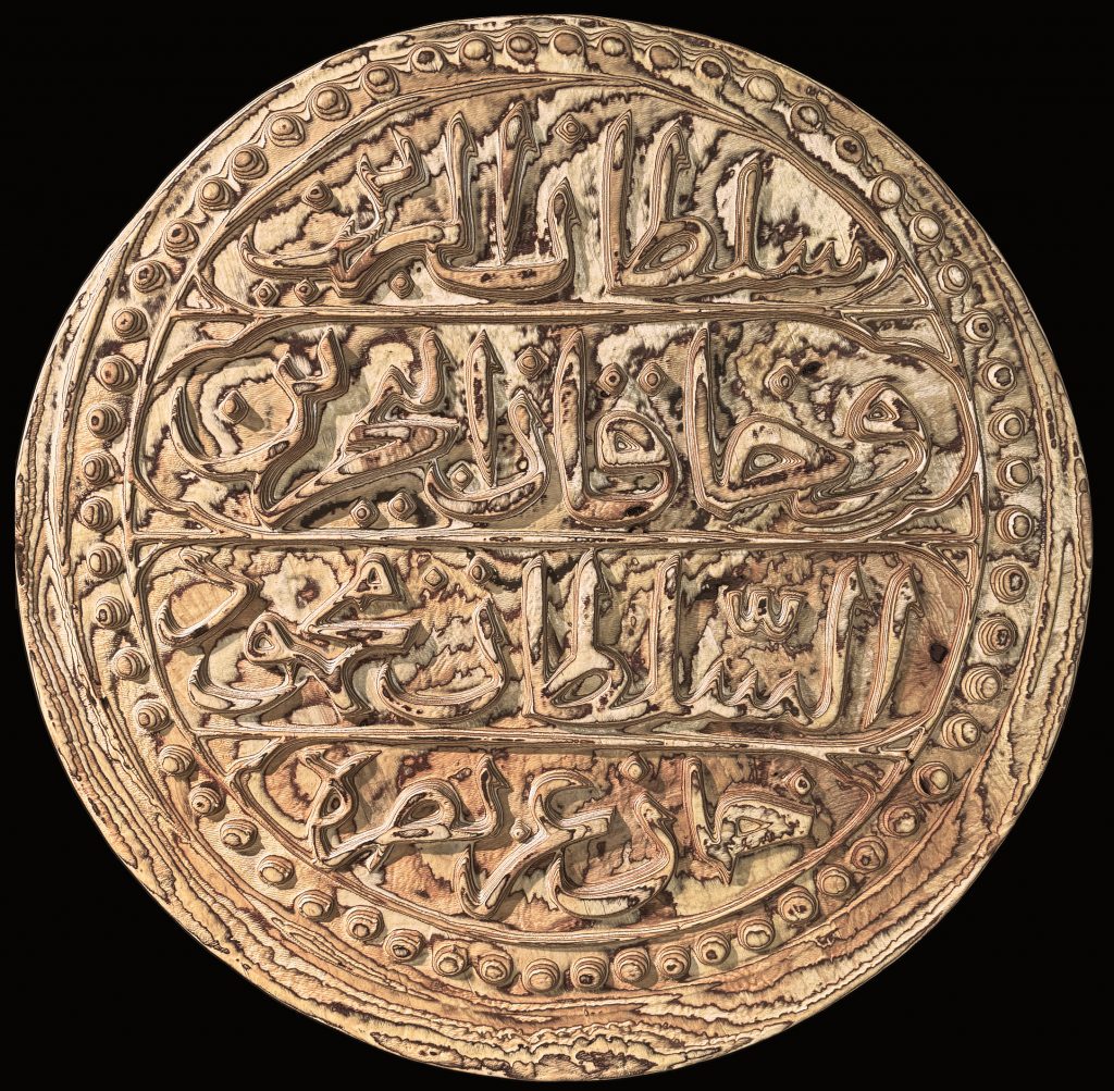
The original silver coin, just 28.7 mm in diameter, was transformed into a one-meter-wide replica carved from birch plywood.
Denomination: 1 Budju
Material: Silver
Width: 28.7mm
Weight: 10.37g
Mint: Algiers
Year: 1239 (1824)
Language: Arabic
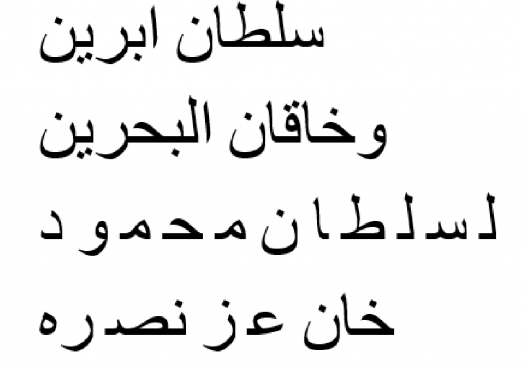
The Arabic inscription reads:
“Sultan of the two lands and ruler of the two seas, the sultan Mahmud Khan, may his victory be glorious.”
Replicating the coin comprised of the following steps:
Capture the Image:
Take a high-resolution, evenly lit, perpendicular photograph of the coin.
The original coin would have been struck by hand, here it has resulted in a slightly misaligned strike that left excess material, or ‘flashing,’ on the lower edges.
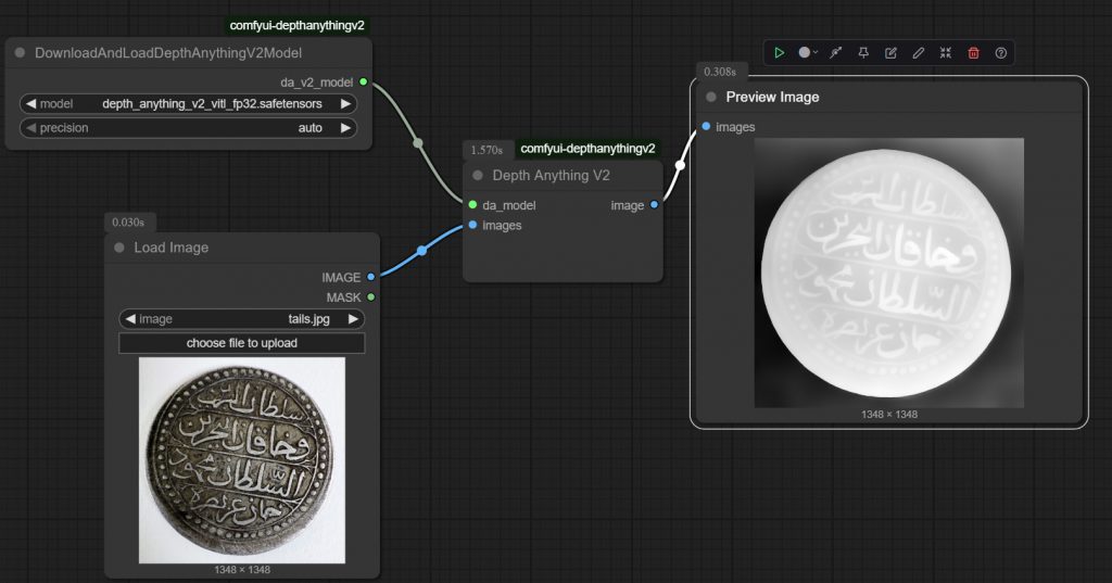
Generate a Depth Map:
Convert the photograph into a grayscale depth map – an image where varying shades of black and white represent the coin’s relief (depth and height).
There are a number of techniques for estimating a depth map from a 2d image; traditional, rule-based / algorithmic techniques – and more recently AI neural networks trained on a huge datasets have proved very effective.
Some examples of these (open source) models are Marigold, Midas, DepthFM. There are online versions of these that can be used – but in this instance DepthAnything was used to process the image locally.
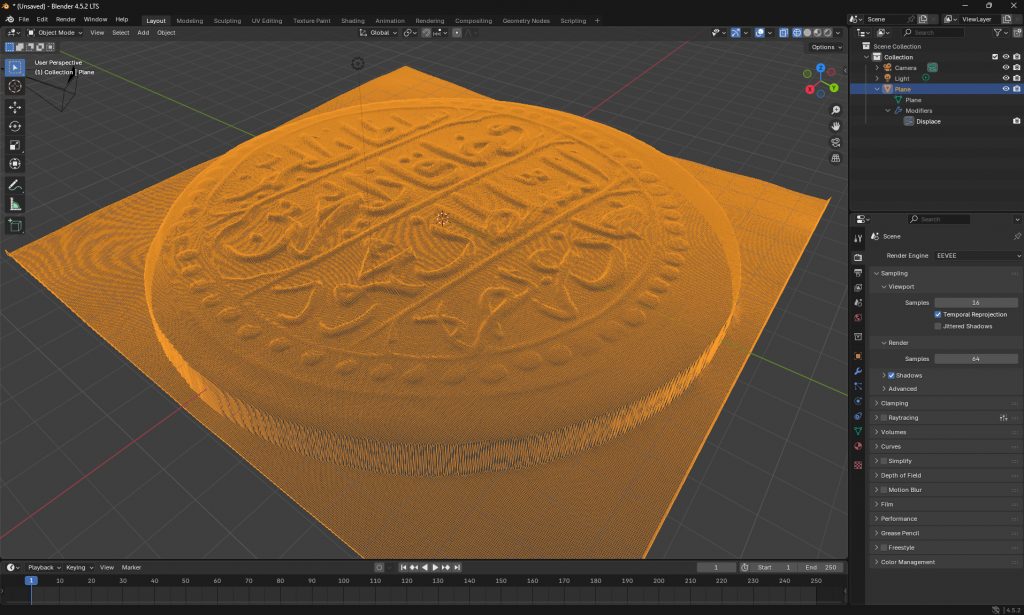
Create a 3D Model
Apply the depth map as a displacement map onto a flat digital model to create a 3D surface.
With the depthmap image as a PNG image, this can be applied as a displacement modifier in most 3D editing software then exported as an OBJ.
• Rhino – HEIGHTFIELD command, select the depthmap file. Increase the sample points to get a finer mesh
• 3d Studio – Select the geometry (cylinder) and apply DISPLACE modifier, load the depthmap image – use the strength parameter to control height of displacement.
• Blender – Add new mesh plane, subdivide the mesh in object mode many times, apply the displace modifier, create in that a new texture and open the depthmap image to apply it.
CNC Toolpath Generation
Import the .OBJ into CAM software to generate the toolpath – these are the digital instructions the CNC machine will follow to take the drill bit around the material fixed on the CNC bed.
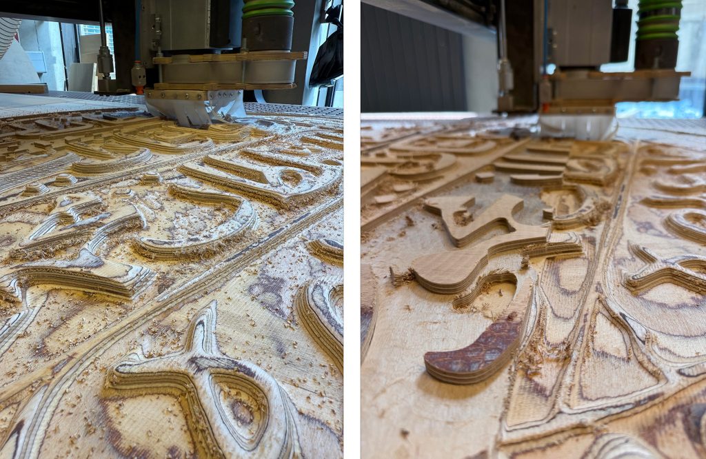
CNC Machining:
Run the CNC operation to carve the 3D coin shape from a block of plywood according to the toolpath.
The CNC machine will perform a two-pass subtractive process: a roughing pass with a larger bit to remove the bulk of the material, followed by a finishing pass with a smaller bit for finer details.
The first pass took around 40 minutes, while the second pass took 6 hours to complete.
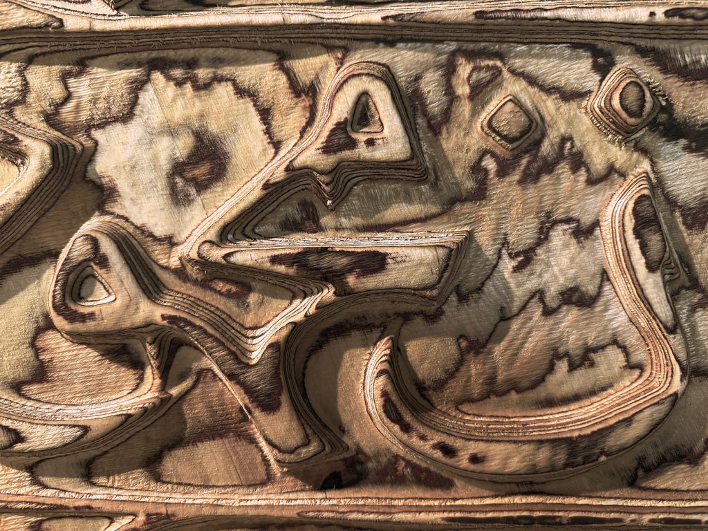
Finishing
Sand down any rough areas on the carved coin and apply Tung oil to finish the wood.
The CNC process can leave fine tool marks, and rough surfaces; sanding smooths these imperfections, revealing the wood’s true character. Tung oil, a penetrating oil finish applied over 3 days, soaks into the wood fibres, making them appear richer and darker. This brings out the grain and enhances the contrast and visual depth of the wood’s natural pattern.
After the Great Exhibition of 1851, the Crystal Palace structure was moved from Hyde Park to Penge Place in South London, now known as Crystal Palace. A railway station and an elaborate subway were also built for it.
The Palace itself burned down in 1936, and the railway station was demolished in 1961, leading to the subway’s gradual disrepair. Around 2010, the Friends of Crystal Palace, Bromley Council, and Historic England initiated a major restoration project. The subway reopened earlier this year.
The vaulted area is directly below Crystal Palace Parade and features 18 stone columns topped by terracotta-and-cream brickwork fanned vaults.
The busy road is about 1.5 meters above the vaults – buses can be seen on the road in this scan.
The same view in elevation
This section is made up of both scanner’s output – the BLK2Go for the closer / colour point clouds and the Hovermap for the longer range street captures
This is an undertaking to replicate an 18th century Ottoman gravestone which is currently held by the Royal Greenwich Heritage Trust.
Michael Talbot, Associate Professor in the History of the Ottoman Empire and Modern Middle East at the University of Greenwich, was informed by the Royal Greenwich Heritage Trust about an “Arabic tablet” which he identified as an Ottoman object and subsequently transcribed and translated the inscriptions on it.
The original tombstone itself is a late-eighteenth century artifact made of limestone or marble featuring Ottoman Turkish inscriptions in the sülüs calligraphic style. The gravestone’s origin is not clear, but it was possibly brought back from Constantinople as a memento by a British officer in the 19th century. The inscription features a poetic composition reflecting the youth and untimely death of its owner.
The tombstone itself measures 72 cm x 21.3 cm x 11 cm thick. The stone is broken at the bottom where it would have originally been set into the ground. It would also have been topped with a carved representation of the headgear associated with the deceased’s rank and profession, likely a turban, indicating a position in the religious-scholarly class.
Replicating the tombstone comprised of the following steps:
Scanning: photograph all sides / angles of the object and utilising photogrammetry to generate an accurate 3d digital model of it.
3D Printing: produce actual-size moulds of the tombstone from the scan model.
Casting: pour Jesmonite (similar to plaster) into the moulds and allow to set
Scanning
Photogrammetry is a process of 3d scanning whereby many photographs of an object are used to create an accurate digital model. Common points in the overlapping photos are identified in order to align them and create a point cloud – a 3D representation of the model as dots in 3d space extracted from these aligned images. This is further refined into a mesh model to form a network of triangles which are lastly “wrapped” with the texture that has been derived from the photographs to provide colour and detail to the 3D surfaces.
To get the best results for use with the photogrammetry software there should be many photos which are sharp, evenly lit – with as little shadow as possible – and capture all sides and angles. Ideally the object would be photographed in a photo-studio with controlled lights and blank backdrop etc, but since this was not possible in this case some soft lighting was brought to site to offset directional shadows from windows.
The model was photographed with a Panasonic Lumix FZ82 (on a tripod) which is a mid-range bridge camera. Manual settings / RAW format, approximately 500 photographs – then post processed in Adobe Lightroom to eliminate any blurred shots and batch edited to further reduce shadows and bump up highlights.
The photogrammetry software used for this exercise is called Reality Capture. Since the tombstone was too heavy to stand up on its end it had to be laid flat, horizontally for one set of photos and then flipped onto its front to capture the other side. Ideally Reality Capture would have automatically detected all the photos as a single object but in this case it generated two separate components: a top and a bottom. To fix this one halve had to be flipped and manually aligned in the software in order to produce a single complete model.
With the model successfully generated it can be exported to a variety of formats for a variety of purposes. For viewing / zooming / spinning the model online it has been exported to Sketchfab this model includes the texture for added realism.
For purposes of 3d printing the model is exported to a common OBJ file format. The texture wrapping step is not important to 3D printing since these printers do not reproduce the model’s colour, so the version used there is effectively monochrome.
3D Printing
Commonly 3D prints are created using PLA or photopolymer resin etc. While these materials recreate accurate models, they can feel light and “plasticky”. For the tombstone it was important to recreate as much as possible the tactility of a stone / marble material and have a weightiness that approaches something more authentic to the original in that respect.
For these reasons instead of printing the model directly, moulds of the model – effectively an inverted version of the 3d scan – were produced, into which a plaster-like material was poured and left to set.
Material used to print the moulds: TPU 95A flexible filament. This means the resulting structure is supple and bendable – strong enough to hold the pour but can be peeled away from the cast once it has set.
3D Printer used: Bambu Lab P1P. The maximum printable area of this printer is much smaller than the size of the tombstone itself meaning the mould needed to be printed as 4 sections and then reassembled for casting. Each of the sections took 18 hours to print. (shorter test section illustrated above with red mould).
Since a full dense model would use a lot of casting material – and also create a very heavy model – only an outside skin of about 10-15 cm of the model was needed to be cast. To achieve this an additional 3d printed core of the tombstone was placed inside the mould in order to cast around it. The final model is lighter and more economic with casting material and retains the proper look and feel – but with a hidden, enclosed, non-dense core.
Casting
The material used to cast the tombstone is Jesmonite – this is a water-based composite material that combines natural materials such as gypsum and resin with various other components, including water-based polymers. It is known for its flexibility, durability, and environmental friendliness compared to traditional resin-based materials. It is also less likely to chip or crack like regular plaster and can be mixed with a pigment to colour the material.
Images below show Jesmonite being mixed with pigments and some experimental, test colours.
The 4 separate 3d printed moulds were taped together to form a continuous mould to be cast into – so the moulds were printed as 4 sections with the casting as a single object which required no reassembly.
The photo above left shows the 3d printed, light core inside the mould while on the right the Jesmonite is poured in to fill the mould with the core embedded inside.
The cast itself sets fairly quickly in about 20 minutes and is then ready to be removed from the mould. The moulds themselves can be re-used to produce more replicas (though the core would require re-printing).
The weight of the replica is initially about a third of the weight of the original, though as the moisture evaporates over a few weeks it becomes somewhat lighter, though still a substantial weight of about 15kg.
A scan of 23 stone heads stored at the Old Royal Navel college in Greenwich.
Carved around 300 years ago by sculptor Robert Jones, around 50 of these heads were commissioned as decorative features for the courtyard of the Painted Hall – originally intended to be built in stone. A financial decision to swap to brick instead meant the stone heads were never used.
The best preserved (and repaired) heads are now on display in the ORNC visitor centre – with two more set into a fireplace in the Queen Mary undercroft. The rest that survive reside in the vaulted undercroft of Queen Anne and make up this scan survey.
Made from Ketton limestone the heads represent mythical characters of the sea (with the addition of British Lion heads). They are stacked up, chipped – some of them quite badly – and staring into the darkness; a haunting sight – and great material for scanning and digital manipulations.
The image below is a laser scan of the vaulted undercroft where the heads are situated – a remnant of the old Tudor Palace of Placentia.
A visit to a vast disused factory in Paris before it is demolished. The old Pouchard Tubes pipe factory was a historic industrial site in Pantin, a suburb of Paris. It was founded in 1927 by the Pouchard family, who specialized in cold deformation and surface treatment of steel tubes for various applications, such as automobiles, boilers, and railways.
Les Grandes-Serres de Pantin: Truss / Gantries
The factory occupies a large area between the railway tracks and the canal de l’Ourcq, and has distinctive glass-roofed halls that gave it the name of “Les Grandes-Serres” (The Great Greenhouses)
Les Grandes-Serres de Pantin: Main Hall
The factory itself closed in 2017 and the site acquired by a real estate developer with plans to transform it into a mixed-use complex with offices, services, shops, restaurants, and a hotel.
Les Grandes-Serres de Pantin: Rotating Gantry Rig
Prior to commencement of the redevelopment the premises were made available as a huge artist space for exhibitions and installations; this scan survey was carried out in cooperation with “Boite à tubes #1, Grandes-Serres de Pantin, 2021”, an electroacoustic work on the industrial sound memory of the site.
The installation was created by Nadine Schütz, a Swiss artist who works in sound and space. She created the work in collaboration with the artist collective Echora.
Les Grandes-Serres de Pantin: Houdini Volume Light EffectsLes Grandes-Serres de Pantin: Houdini Point Size Experiments
The sound installation itself is located in a small control cabin in the Grande Halle of the Grandes-Serres which has been perforated with a variety of metal tubes of different sizes. Each tube plays a different sound, creating a cacophony of industrial noises which act as powerful reminder of the industrial past of the Grandes-Serres site.
Les Grandes-Serres de Pantin: Adjacent Row of Lime Trees
While the many lime trees that surround the site cannot be relocated, the intention is for their sculpture-grade wood to be repurposed within the new development.
Les Grandes-Serres de Pantin: Cyclone 360 Orthographic Projection
The Brunel Museum tunnel, also known as the Thames Tunnel, is a museum in Rotherhithe, SE London, consisting of the engine room and the shaft down to the tunnel.
Built by Marc Brunel and his son Isambard Kingdom Brunel, The Thames Tunnel was the world’s first underwater tunnel for pedestrians. When the tunnel opened in 1843, it was hailed as the 8th Wonder of The World.
By employing a pioneering tunnelling shield and other novel techniques, the Brunels encountered waterlogged ground, fires, and the ever-present threat of the River Thames above. Their success paved the way for future underwater tunnels and underground transportation systems.
The shaft is now sealed over, as the tunnel is now used by Overground trains – though the trains travelling between Rotherhithe and Wapping stations can still be felt and heard.
These two images illustrate the approximate location of the the train tunnels below the shaft seal.
Animation of Ortho camera descending through the site
Nunhead Cemetery, established in 1840, stands as a significant Victorian burial ground in South London – one of the “magnificent seven” of London’s cemeteries. This historical site is characterized by its Gothic-style tombs, sprawling landscape, and diverse collection of monuments.
The Cemetery underwent a period of neglect and closure in the late 20th century due to financial constraints, leading to sporadic maintenance and overgrowth of vegetation. The burial grounds became engulfed by nature as trees, shrubs, and wildflowers obscured the graves and pathways, creating an eerie yet captivating atmosphere. This phase of overgrowth contributed to the cemetery’s unique charm, blending historical significance with a reclaimed natural landscape. In recent years, efforts have been made to restore and maintain the cemetery, preserving its historical allure while balancing its enchanting overgrown appeal.
The chapel in the centre of the cemetery was designed by Thomas Little in a Gothic style, and is a striking centerpiece amidst the serene landscape. Completed in 1842, its design features intricate details, including pointed arches, decorative stonework, and a dramatic spire that adds to its grandeur.
Originally serving as a place for funeral services and gatherings, the chapel fell into disuse and disrepair during periods of neglect. In 1976 after an arson attack the interior and roof were completely destroyed and the catacombs looted.
A Captivate exhibition showing works and models in and around Maritime Greenwich and beyond.
Captivate Spatial Modelling Research Group is making synthetic compositions of the entire Maritime Greenwich World Heritage Site. Never before seen views of Queen’s House, St Alfege Church, the Old Royal Naval College, Greenwich Park, the Painted Hall and the wider Maritime Greenwich buffer zone. These views expand into three dimensions Canaletto’s own curiously synthetic composition of 1750-52, ’Greenwich Hospital from the north bank of the Thames’ (at Royal Museums Greenwich).
Captivate uses a variety of remote sensing technologies such as 3D scanning, photogrammetry, ground penetrating radar, hyper-spectral frequencies and drone surveys. The ensuing data accumulates into vast point clouds, a Milky Way of millions, billions, of points. These multitude points are universally though unevenly distributed as points of data, think of the cumulations of stars in the firmament above.
As with a vision in a swirling mist, there are thickenings and thinnings amid the confusion, densities fizzing at the edges, unstable, playful, dissolving/resolving into ghostly forms. Wildly fluctuating architectural inventions, oscillations of shivering veils, x-ray labyrinths and parallel worlds.
The familiar made strange revealing perpetually evolving pointillist views of Greenwich.
The foot tunnel beneath the Thames connecting Greenwich in Southeast London to the Isle of Dogs.
27/7/22 : 5.00AM
Leica BLK2GO SLAM Scanner
Single scan / 20 minutes
Rendered with 3DS Max / V-Ray
The tunnel was built in 1902, is 370 metres long and 15 metres deep.
The south shaft has 100 steps, the north shaft is a little shorter with just 88 steps.
A section of the tunnel was damaged by a bomb on the first night of the blitz during the Second World War in 1940. The repairs included this exposed metal ring segment.
Point clouds may be opened easily enough in Blender but they will not render out unless particular attributes have been assigned to the point cloud using Blender’s Geometry Nodes capability – essentially a real, renderable 3d primitive is located at each point.To import a point cloud the format must be PLY; either export from the point cloud software as PLY or use CloudCompare to open the point cloud and resave as PLY. This may also be a good opportunity to optimise the point cloud file with the CloudCompare Subsample tool – make it smaller; point clouds, particularly from laser scanners, can be very large and will cause performance issues even on high spec machines.
1. In Blender [3.1 or higher] in a new empty file select :
FILE - IMPORT - Standford (.PLY)
and browse / select the point cloud file
In this example a relatively small file has been imported – this export is from the iPhone Lidar App EveryPoint (Pressing CTL-ALT-Q swaps it to 4 viewports of the point cloud).
If you do not want / do not have colours in your point cloud then you can skip step 2 and go straight to step 3
2. Change to the SHADING tab along the top and click NEW for a new material. Give this a name like PCMaterial.
Now some particular attributes need to be added: from the middle bar click
ADD - INPUT - ATTRIBUTE
Drop this node to the left and in the name field call it Col – note, must be capital “C”
To the right of this add another node for the colour value:
ADD - COLOR - HUE SATURATION
And set the Saturation field to 2.
These nodes can now be linked by dragging from the input / output points. Drag Color to Color and Color to Base Color so the node arrangement looks like this:
3. Switch to the GEOMETRY NODES tab from the top of the screen and click NEW in the middle bar to create a base Group Input and Group Output.
Create 2 new instance nodes (if you drop these on the line they will automatically link up properly)
ADD - INSTANCE - INSTANCE ON POINTS
and to the right
ADD - INSTANCE - REALIZE INSTANCES
to end up with this layout:
Next will be another node that will define the real, renderable object that will be at the location of each point in the point cloud – for this example a cube.
ADD - MESH PRIMITIVE - CUBE
Start with giving the cube the dimensions of 0.01 – these figures will likely need to be altered to fit whatever scale the point cloud is suited for.
Link the Mesh OUT to the Instance IN – but first note the following point:
This is where the point cloud will display as a proper renderable form – BUT it can take a long time depending on size of point cloud. Save first, close other applications, etc.
The rendererable point cloud will now show in the viewport (to speed up this view, or to eliminate viewing errors due to location of the light you can choose to view it as a simple solid form by clicking the solid circle icon, top right hand corner).
The X Y Z dimension of the cube in the cube node can be changed – and the model will update accordingly.
4. Finally the colour (if any) of the point cloud can be brought in by adding another node and linking to the material made in step 2:
ADD - MATERIAL - SET MATERIAL
Drop this on the Mesh-to-Instance link line and in the bottom field type the name the material was given in the first step “PCMaterial”
Even if there was no colour info in the point cloud this node can be useful for assigning a material to it for colour / shininess / transparency etc.
NOTE: Material operations will only render properly with the Cycles renderer. Eevee render will render much more quickly – but it will be flat colours (which may be fine for mono point clouds).
Credits and thanks to Michael Prostka for YouTube guide and development of PLY import