


“Waypoints” is our Virtual Reality (VR) conversion tool to enable users to view their 3d models in real time with a VR headset.
The software will translate files from standard 3D packages such as 3D studio, Blender, Rhino etc into a format that can be viewed on a VR Headset – or rather a mobile phone in a suitable headset holder like Google Cardboard. The converted file is loaded into the browser window of a mobile phone and fitted inside the headset where it will respond to head movement to allow the user to look around their design. Additionally “waypoints” are generated around the model to let users navigate around the VR space; simply “stare” at one of these points to select it, then that point is moved towards.
Instructions
Waypoints Beta r1 Documentation
This is beta software and may contain bugs.
You will need:
- A copy of Waypoints.
- A Windows PC and a mobile device connected to the same wifi network.
- A mobile browser with WebGL support (most modern smartphones and tablets will have this)
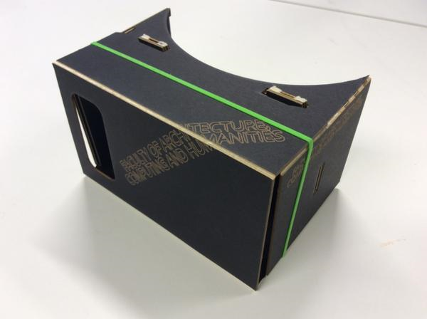
- A VR viewer for your mobile device, such as Google Cardboard.
- Mongoose Binary Free Edition (‘the easiest to use web server on the planet’). Download it from https://www.cesanta.com/mongoose.
Getting Started (Windows 7)
Copy the Mongoose Free executable file to a newly created folder in an accessible location such as the Desktop.
Open Waypoints. It will start up with a basic demo scene already loaded. Click ‘Export HTML’ (at the bottom of the panel on the right). Save the file in your Mongoose folder.
Minimise Waypoints for the moment and browse to your Mongoose folder (it should now contain a copy of Mongoose Free and a file called index.html). Double click the Mongoose icon and index.html will open on your computer. Ignore that, and check the system tray for a yellow Mongoose icon. Click the icon, and look for a menu entry that begins ‘Go to my address:’. Carefully type the given address into the browser ON YOUR MOBILE DEVICE and the demo VR scene should load. Attach your VR viewer to your device and you should be good to go (you may need to turn around to find the scene). Keep the floating crosshair aligned with one of the cyan spheres for one second (until it fades out) and your virtual viewpoint should animate to that location.
So long as Mongoose is running, all you need to do to update the scene on your device is make changes in Waypoints, overwrite index.html, then refresh the browser on your device. Once set up, it should be quick and easy to experiment using this method. To stop Mongoose, just click its icon in the system tray and choose ‘Exit’.
Note: University machines will require administrator permission to run Mongoose properly as it requires firewall changes; you will need to get one of the technical staff to open a port for you. Alternatively use your own laptop which you will (presumably) have administrator access to.
Importing Models and Textures
Drag and drop a 3D model (.obj format) or a texture (.jpg or .png) onto the window to replace the currently loaded model or texture. To import multiple objects, you will need to export them from your 3D modelling software as a single .obj file. Waypoints does not currently import normals or provide realtime lighting, so your model must be UV unwrapped and textured. Lighting and materials can be ‘baked’ into a single texture as per the demo scene. The pixel dimensions of your texture should ideally be powers of two (256, 512, 1024 etc) and your texture should not exceed 2048 x 2048 pixels in size. 1024 x 1024 is the recommended maximum, and should allow for a reasonable amount of detail.
Instructions on how to generate UV mapped textures varies between 3D applications; see this link for instructions on Baking Materials in with Blender
Top Viewport
The top viewport gives an overview of your scene.
- Left mouse button – rotate view
- Middle mouse button (or mouse wheel) – dolly in/out
- Right mouse button – track left/right, pedestal up/down
Left click a waypoint to select it, and drag the transform gizmo to move it around.
- Red arrow – x adjustment
- Green arrow – y adjustment
- Blue arrow – z adjustment
- Yellow plane – xy adjustment
- Cyan plane – yz adjustment
- Magenta plane – xz adjustment
Note that the coordinate system used (which is dictated by WebGL) may differ from your 3D modelling software.
The amber coloured pyramid extending from the currently selected waypoint represents the extents of the view from that location. This view is always displayed in the bottom viewport.
Bottom Viewport
The bottom viewport shows the view from the selected waypoint. Drag the view to look around and find out what will be ultimately be visible by turning your head in the exported VR scene.
Panel on Right
Drag values up or down to modify them, or click to select then edit using the keyboard.
- World > Hue / Saturation / Brightness – Set the background colour of the scene.
- Waypoints > Hue / Saturation / Brightness – Set the colour of the spherical markers
- Waypoints > Sphere Diameter – Set the diameter of the spherical markers. If your waypoints are spaced a long way apart, or you have chosen a wide angle focal length setting, you may need to increase this to enable the viewer to easily get a ‘lock’ on distant waypoints using the floating crosshair.
Selected Waypoint > X / Y / Z – Another way of positioning the selected waypoint.
Camera > Pan / Tilt – Rotate the camera. These settings will have no effect on the exported scene, as the camera orientation will be controlled by device orientation.
Camera > Focal Length – The focal length of the camera – in other words, ‘zoom’. Lower values = wide angle lens / wide field of view / exaggerated perspective. Higher values = telephoto lens / narrow field of view / flattened perspective.
Stereo > Separation – The distance between the two virtual cameras used to create the stereoscopic effect. Increasing this will increase the impression of depth in the exported scene, but at some point it will become difficult or impossible for your brain to fuse the left / right images.
Stereo > Projection Plane Distance – Objects closer than this will appear to pop out of the screen toward you, while objects further away will appear to be ‘behind’ the screen.
Not all combinations of Focal Length, Camera Separation, and Projection Plane Distance will work, and small changes can quickly destroy the 3D effect or make for an unpleasant viewing experience. Aim for viewing comfort rather than ‘extreme 3D’. Further technical info on these parameters can be found here:
http://paulbourke.net/stereographics/stereorender/
Export > Export HTML – Export your edited scene for viewing using Google Cardboard or similar (see ‘Getting Started’ above).