


CHANGING NOZZLE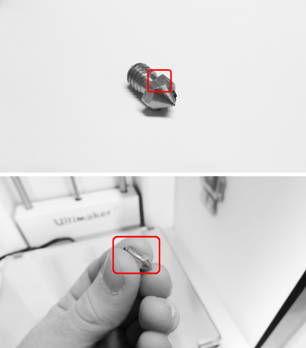

The box contains 4 sizes of nozzles, the smaller allows for more detail to be printed but may increase time exponentially. The bigger the size of the nozzle, the faster it will print and overall quality of big elements will not be affected.
The size of the nozzle is engraved on one of its sides. The physical size is small and nozzles can get easily lost so handle with care.
The socket wrench key tool available at the workshop is used to change nozzles.

FILE PREPARATION

1. The file we expect to rapid prototype should preferably be in .STL format.
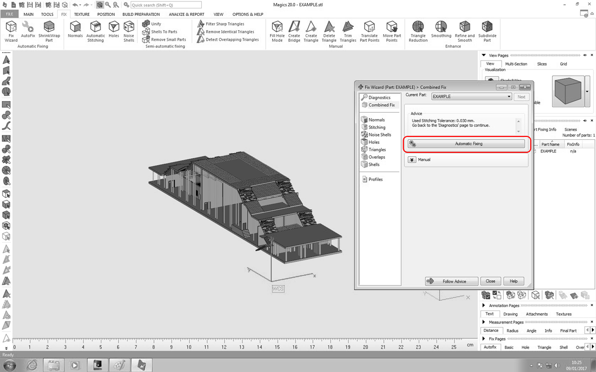
2. The file may need to be fixed – this can be done by using a specialised software to repair mesh models; e.g CURA software for the Ultimaker, Magics (available in the workshop) or using the Microsoft 3d print repair tool available online here
https://netfabb.azurewebsites.net/index.php
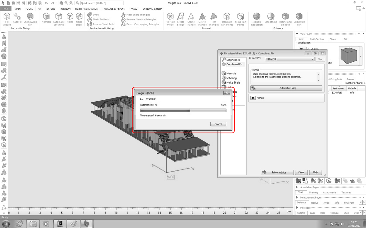
3. The process of fixing is not guaranteed to make the 3D model suitable. It highly depends on how the file is modelled. It must be watertight and have no glitch surfaces.
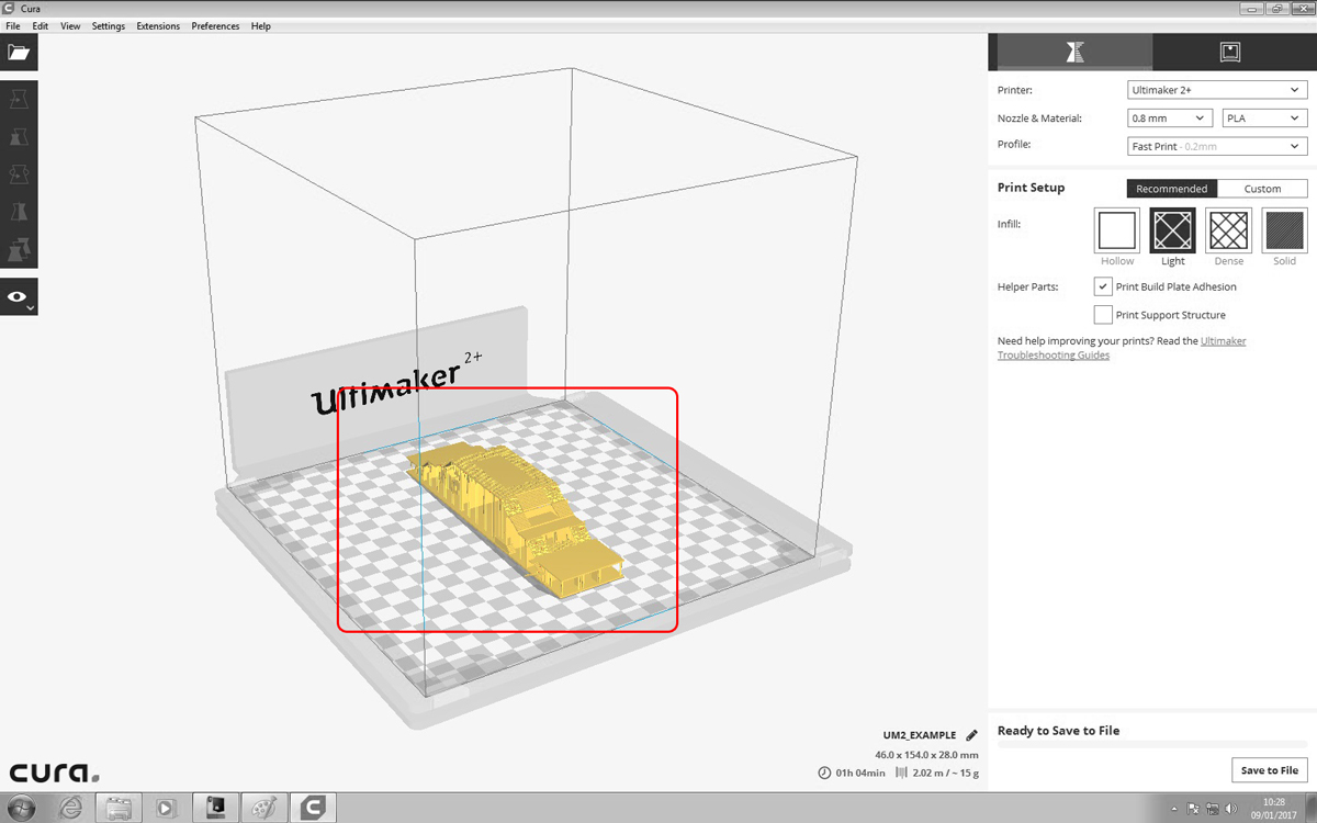
4. The corrected 3D model will appear in gold once opened in the CURA software. It will show a time estimate in the right-hand corner and give options to adjust material thickness and nozzle sizes.
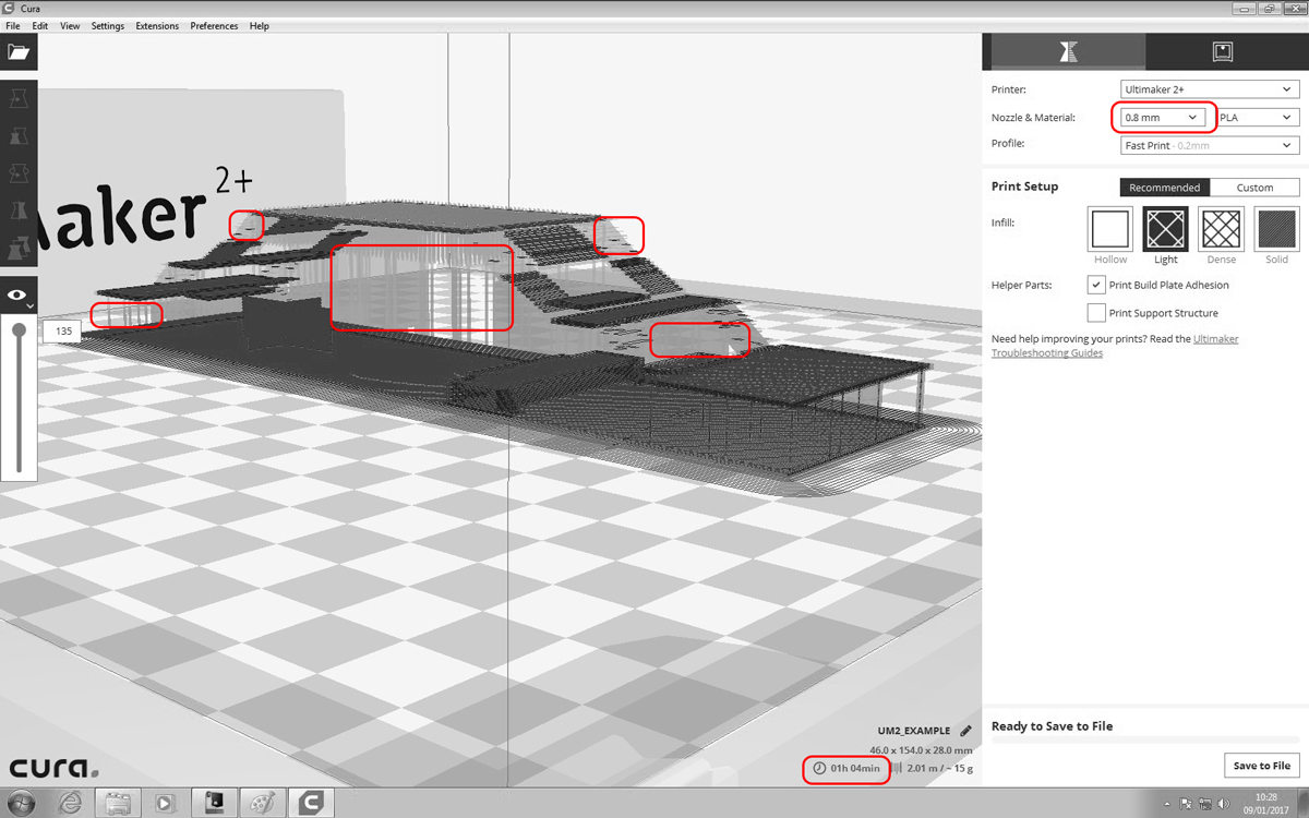 5. If the nozzle size is too big this may mean that smaller components will not be prototyped – this can be indicated by the greyed-out areas.
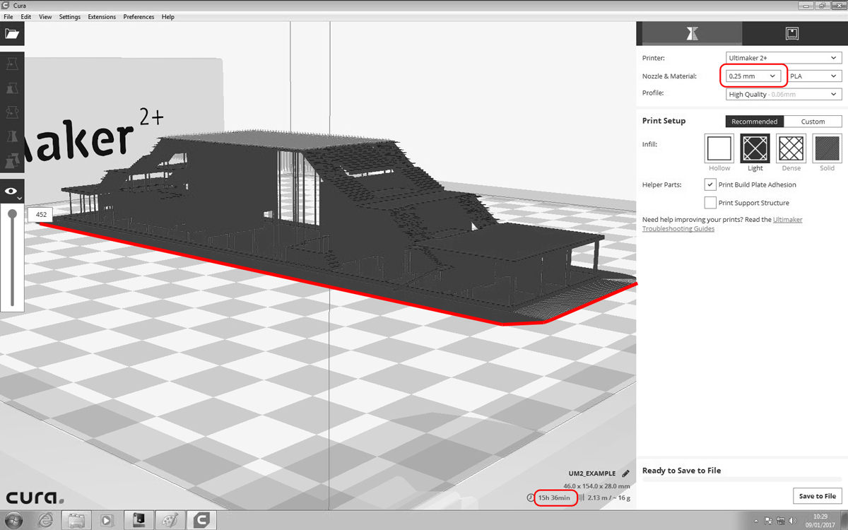
6. Changing the nozzle to a smaller size might consume more production time but elements as small as 1 mm are possible to print.
 7. The Cura software will then generate a file with all the necessary settings that can be read by the Ultimaker printer.
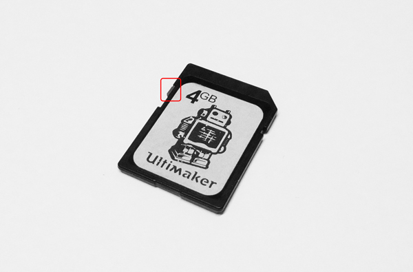
8. Take the SD card on which the file is saved out from the PC.
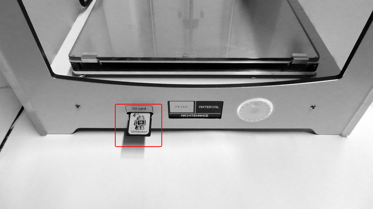
9. Then insert the SD card into the machine.
MATERIAL PREPARATION
 1. Once the card is in, do not press print straight away. The settings of the file might not match the machines current configuration of nozzle size, material type and printing table.

2. Instead, start by changing the material.The rolls of plastic on disposal are grey, black and white. If you decide to bring your own please make sure it matches the machines capabilities by consulting this with the workshop manager.
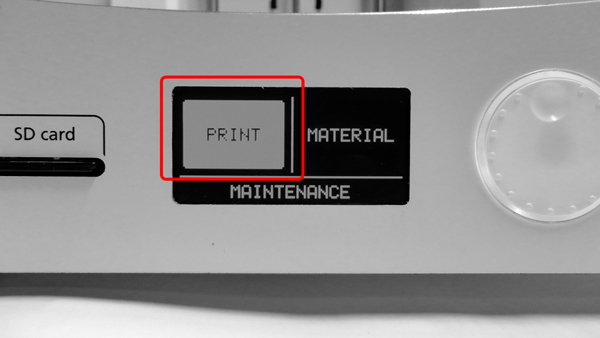
3. If MATERIAL is clicked the print head will be heated and the material pushed out of the nozzle.

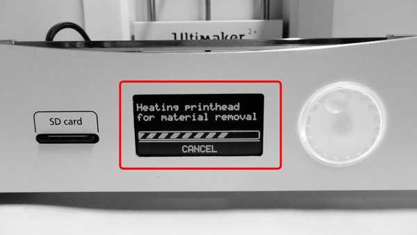
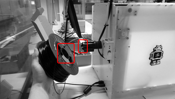
4. The machine will then prompt you to remove the material roll from the back of the printer.
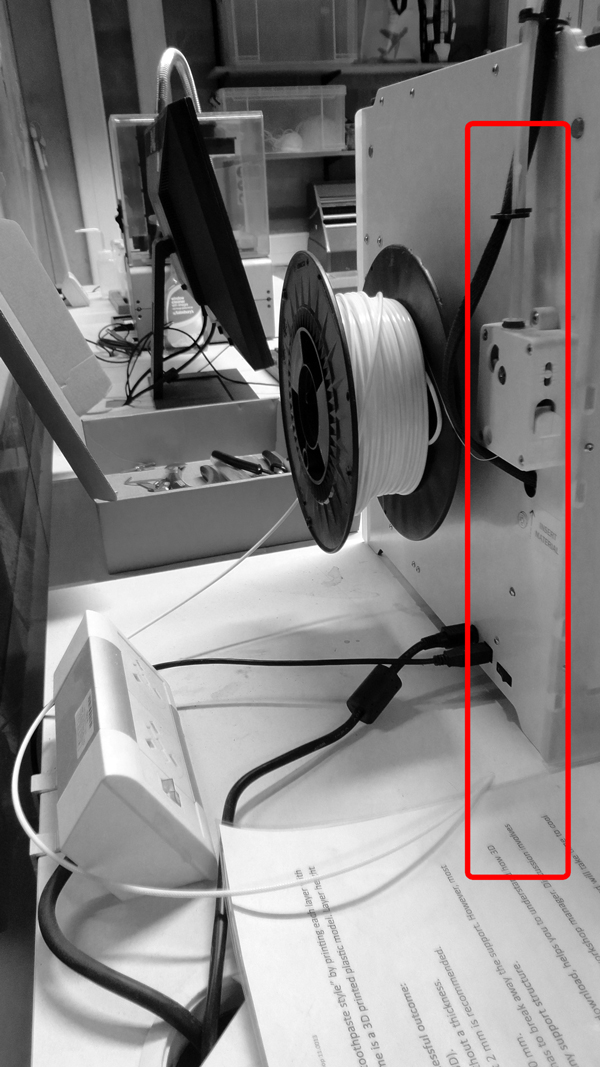
5. This is easily done by pulling the material out of the feeding tube and pushing out the roll from the axis.
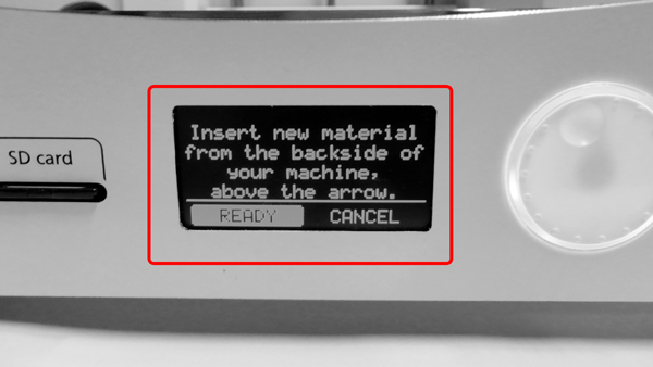
6. The little screen will ask the new material to be inserted. Do not press READY yet.
7. Push in the new roll onto the axis.

8. Unroll a length of material sufficient to allow you to easily insert it inside the feeding tube opening.
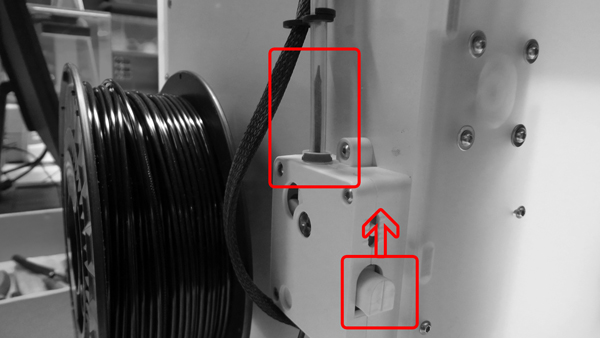
9. Press and hold the white button while inserting the material. Once you see the material in the transparent feeding tube let go of the white button.
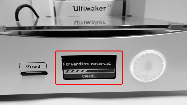
10. Press ready and a message with progress line will appear meaning the material is being automatically fed into the tube. Wait until it reaches the print head.
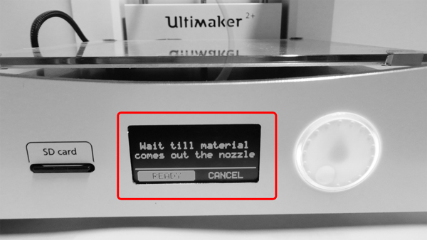
11. Do not press ready until the colour of the plastic flowing out of the nozzle is uniform. Then press READY to stop the machine from wasting material.

12. The preheated print head will flow melted plastic. Wait for the melted plastic stripe to acquire the colour of the current material.

13. Press OK to confirm that the selected material is PLA.
BUILD-PLATE PREPARATION
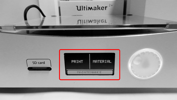
1. To start configuring the build plate table navigate to MAINTANANCE.
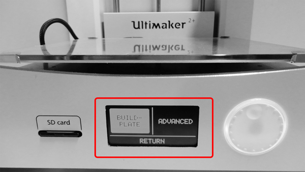
2. Within the menu choose BUILD-PLATE.
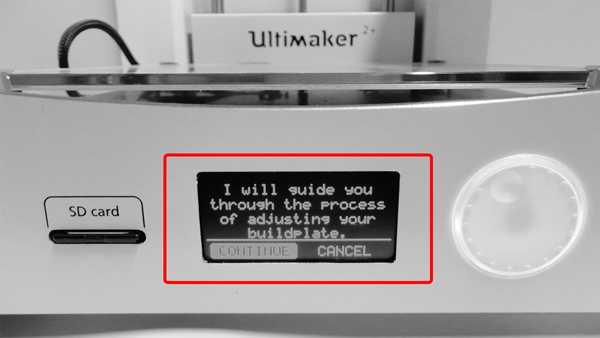
3. The machine will guide you through the process of adjustments.
4. Rotating the white button will make the vertical position of the plate change.
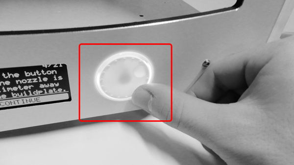
5. Gently try rotating the button clockwise or anticlockwise. Do not press the button, pressing means selection and the current function will end.

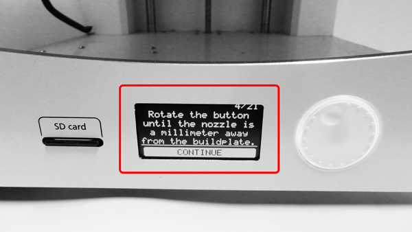
6. The first step will adjust the table so that the space between it and the nozzle is 1mm; so pick a material that is 1mm thick.
7. During the rotation of the button place the material below and start adjusting accordingly so that the nozzle barely scratches the 1mm material. Then press the button to repeat that for the rest of the area of the build plate.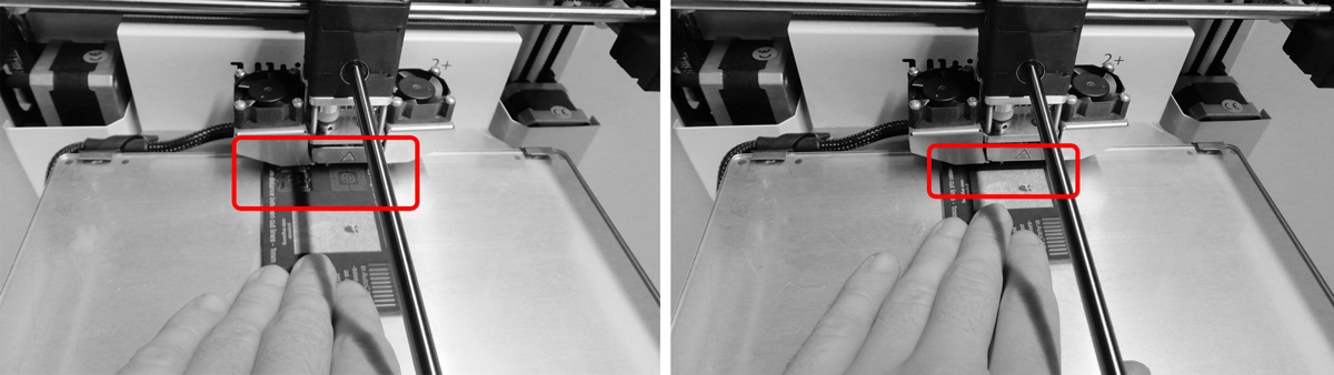
8. This action is done to both left and right corners toward the viewer but this time the bed is adjusted using the spring screws. Loosening the screw will mean the table top will go up. The distance away from the nozzle and the top should again be 1mm and the material must be allowed to move freely between only having little resistance.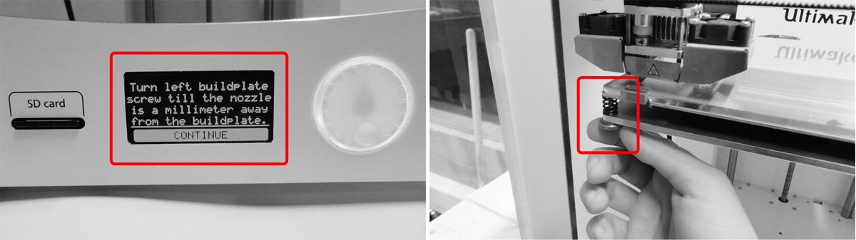
9. Adjusting the right corner is the last action before the final fine-tuning process.
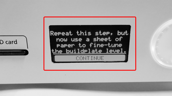
10. The machine will ask you to finish the process of configuring the build-plate with the final steps which are the same as the tuning done with 1mm but this time with a material with the thickness of plain sheet of paper.
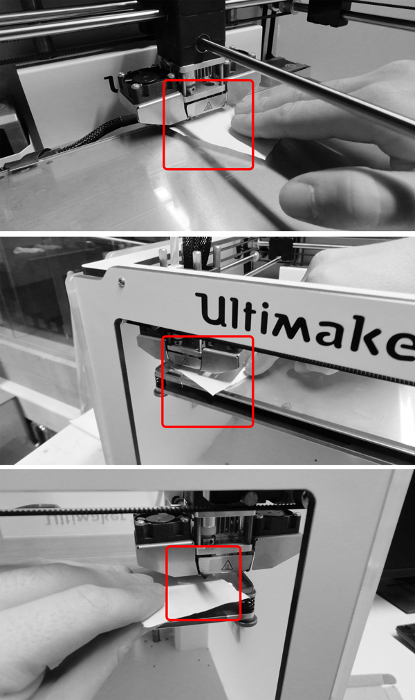
11. Take a small piece of plain paper and repeat the steps. Remember – there should only be little resistance while moving the material in the space between the bed and the nozzle.
PRINTING PREPARATION
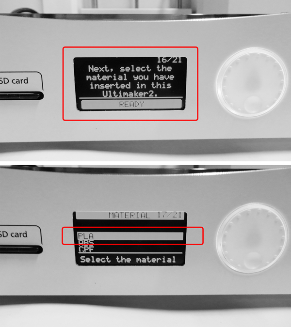
1. The machine asks for a confirmation of the material in order to check. Choose the right material, usually PLA.

2. The machine will say it is ready to print.
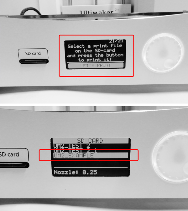
3. The final step is to pick the name of the file of the model which will be prototyped. Press the button on the highlighted name and the machine will start processing the model. After a short time it will raise the build plate and start laying melted plastic building horizontal layers. The time left will be displayed on the screen.